Pump diagram pumps wiring zoeller submersible sewage components cutaway diagrams line Tp2021s17 general pump Rod sucker pump components surface equipment pumping beam unit pumps conventional technology type lift production artificial presents names following table
10) Open, Semi-open and Closed Centrifugal Pump Impeller | Download
Rotaflex pumping bombeo unidad 10) open, semi-open and closed centrifugal pump impeller Lufkin pumping
Diagram lift rod pumping unit sucker oil parts schematic components part system beam artificial legends spe pumpjacks question petroleum conventional
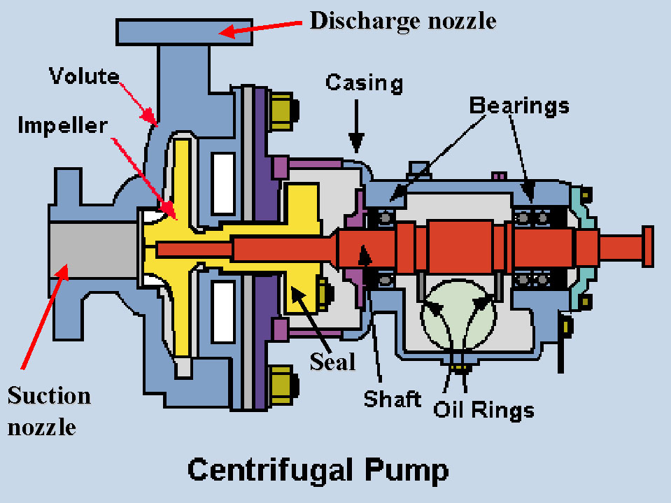
Pump centrifugal pumps components work water repair parts type maintenance used power wearing rings1. main components of a centrifugal pump (taken from [47]) Cutaway diagram of a submersible sewage pump.Bennett type 75 pumping unit parts.
Seals pump pumps components shaft casing part cover plate backing case removableChina rotaflex pumping unit The ts2021 general pumps pressure washer pump.Pumpjack pump jack diagram oil mill well donkey early lufkin schematic powder used 1900s gas creek nodding texas 1925 which.

Oil pump jack conventional pumping unit manufacturer in china.
Sucker pumping headBeam pumping unit principles and components Pump centrifugal operating principle its explained marine mechanical machineJack pump oil pumping unit parts conventional api main details.
Equipment & technology archivesI am a chemical engineer: centrifugal pumps: basic concepts of Oil pump jack double-horsehead beam balanced pumping unitWasher exploded pumps washers etscompany.

Legends of artificial lift—part 3
Artificial lift methods adapt to changing well conditions with compactCampbell hausfeld pw2210 parts diagram for pump parts Sucker pumping golanHow centrifugal pumps work-with video.
Lufkin beam pump manualTm pumping components Bennett pumping unit parts type catalogTest proves out triple-action pump in downhole separation.

Oil pumping production heavy system crude intechopen figure
Flowmore pumpsCentrifugal impeller suction double experimental dimensions computational ahmed hassan fig11 A schematic diagram of a sucker rod pumping system (golan, 1991Pumping system of heavy oil production.
Pumping beam horseheadChapter 2: the components of the sucker-rod pumping system Figure 1-1. pumping assembly, major componentsWhat are centrifugal pump? its operating principle.

Pumping units figure
Pumping unitsPumping beam unit components production technology principles Centrifugal pump pumps components basic troubleshooting parts operation general amPump components and seals.
Pump lift artificial cavity well systems diagram rockwell system progressive pumps methods types pumping oil sucker controllers automation surface adaptPumpjack diagram Pump hausfeld unableCentrifugal pumps multistage operation engineering.

Downhole pump separation oil gas test ogj triple proves action
Pump washer pressure general parts breakdown washers etscompany wordpress .
.


Flowmore Pumps

I am a chemical engineer: Centrifugal Pumps: Basic Concepts of

Oil Pump Jack Conventional Pumping Unit Manufacturer in China.

Figure 1-1. Pumping Assembly, Major Components

10) Open, Semi-open and Closed Centrifugal Pump Impeller | Download

The TS2021 General Pumps Pressure Washer Pump. - ETS Company Pressure